_1.png)


KS0165
Nuevo
Módulo Robotale Scratch. Marca Keyestudio.
El Robotale Scratch de Keyestudio se utiliza con Arduino Nano.
Utilizando el lenguaje de programación Scratch, puede crear fácilmente programas interactivos simples con Arduino o crear programas basados en la entrada de Arduino desde los sensores.
Keyestudio Robotale Scratch incorpora un sensor de luz, un sensor de sonido, un botón y un control deslizante, así como 4 entradas adicionales que pueden detectar resistencia eléctrica a través de cables. Diseñado para educadores y principiantes, el keyestudio Robotale Scratch es una buena manera de entrar en los fundamentos de los sensores de programación y lectura.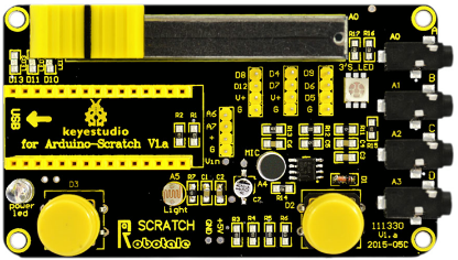

1. Conecte la placa de desarrollo de Nano a la computadora, utilice IDE de Arduino para la carga de firmware.
2. Abra S4A, haga clic en "Costumes" -Importe para importar nuevos costumes.
3. Haga clic en "Script", escriba la secuencia de comandos de control utilizando bloques del grupo de control.
4. Después de completar la secuencia de comandos de control, haga clic en el botón ![]() para ejecutar la secuencia de comandos.
para ejecutar la secuencia de comandos.

// NEW IN VERSION 1.5:
// Changed pin 8 from standard servo to normal digital output

// NEW IN VERSION 1.4:
// Changed Serial.print() for Serial.write() in ScratchBoardSensorReport function to make it compatible with latest Arduino IDE (1.0)

// NEW IN VERSION 1.3:
// Now it works on GNU/Linux. Also tested with MacOS and Windows 7.
// timer2 set to 20ms, fixing a glitch that made this period unstable in previous versions.
// readSerialport() function optimized.
// pulse() modified so that it receives pulse width as a parameter instead using a global variable.
// updateServoMotors changes its name as a global variable had the same name.
// Some minor fixes.

// Thanks to Jorge Gomez for all these new fixes!

#define TIMER2_PRELOAD 100

char outputs[10];
int states[10];

unsigned long initialPulseTime;
unsigned long lastDataReceivedTime;

volatile boolean updateServoMotors;
volatile boolean newInterruption;

void setup()
{
 Serial.begin(38400);
 Serial.flush();
 configurePins();
 configureServomotors();
 lastDataReceivedTime = millis();
}

void loop()
{
 if (updateServoMotors)
 {
   sendUpdateServomotors();
   sendSensorValues();
   updateServoMotors = false;
 }
 else
 {
   readSerialPort();
 }
}

void configurePins()
{
 for (int index = 0; index < 10; index++)
 {
    states[index] = 0;
    pinMode(index+4, OUTPUT);
    digitalWrite(index+4, LOW); //reset pins
 }

 pinMode(2,INPUT);
 pinMode(3,INPUT);

 outputs[0] = 'c'; //pin 4
 outputs[1] = 'a'; //pin 5
 outputs[2] = 'a'; //pin 6
 outputs[3] = 'c'; //pin 7
 outputs[4] = 's'; //pin 8
 outputs[5] = 'a'; //pin 9
 outputs[6] = 'd'; //pin 10
 outputs[7] = 'd'; //pin 11
 outputs[8] = 'd'; //pin 12
 outputs[9] = 'd'; //pin 13
}

void configureServomotors() //servomotors interruption configuration (interruption each 10 ms on timer2)
{
 newInterruption = false;
 updateServoMotors = false;

 TCCR2A = 0;
 TCCR2B = 1<<CS22 | 1<<CS21 | 1<<CS20;
 TIMSK2 = 1<<TOIE2; //timer2 Overflow Interrupt
 TCNT2 = TIMER2_PRELOAD; //start timer
}

void sendSensorValues()
{
  int sensorValues[6], readings[5], sensorIndex;
    for (sensorIndex = 0; sensorIndex < 6; sensorIndex++) //for analog sensors, calculate the median of 5 sensor readings in order to avoid variability and power surges
    {
      for (int p = 0; p < 5; p++)
        readings[p] = analogRead(sensorIndex);
      InsertionSort(readings, 5); //sort readings
      sensorValues[sensorIndex] = readings[2]; //select median reading
    }

    //send analog sensor values
    for (sensorIndex = 0; sensorIndex < 6; sensorIndex++)
      ScratchBoardSensorReport(sensorIndex, sensorValues[sensorIndex]);

    //send digital sensor values
    ScratchBoardSensorReport(6, digitalRead(2)?1023:0);
    ScratchBoardSensorReport(7, digitalRead(3)?1023:0);
}

void InsertionSort(int* array, int n)
{
  for (int i = 1; i < n; i++)
    for (int j = i; (j > 0) && ( array[j] < array[j-1] ); j--)
      swap( array, j, j-1 );
}

void swap (int* array, int a, int b)
{
  int temp = array[a];
  array[a] = array[b];
  array[b] = temp;
}

void ScratchBoardSensorReport(int sensor, int value) //PicoBoard protocol, 2 bytes per sensor
{
  Serial.write( B10000000
                | ((sensor & B1111)<<3)
                | ((value>>7) & B111));
  Serial.write( value & B1111111);
}

void readSerialPort()
{
  int pin, inByte, sensorHighByte;

  if (Serial.available() > 1)
  {
    lastDataReceivedTime = millis();
    inByte = Serial.read();

    if (inByte >= 128) // Are we receiving the word's header?
    {
      sensorHighByte = inByte;
      pin = ((inByte >> 3) & 0x0F);
      while (!Serial.available()); // Wait for the end of the word with data
      inByte = Serial.read();
      if (inByte <= 127) // This prevents Linux ttyACM driver to fail
      {
        states[pin - 4] = ((sensorHighByte & 0x07) << 7) | (inByte & 0x7F);
          updateActuator(pin - 4);
      }
    }
  }
  else checkScratchDisconnection();
}

void reset() //with xbee module, we need to simulate the setup execution that occurs when a usb connection is opened or closed without this module
{
  for (int pos = 0; pos < 10; pos++)  //stop all actuators
  {
    states[pos] = 0;
    digitalWrite(pos + 2, LOW);
  }

  //reset servomotors
  newInterruption = false;
  updateServoMotors = false;
  TCNT2 = TIMER2_PRELOAD;

  //protocol handshaking
  sendSensorValues();
  lastDataReceivedTime = millis();
}

void updateActuator(int pinNumber)
{
  if (outputs[pinNumber] == 'd')  digitalWrite(pinNumber + 4, states[pinNumber]);
  else if (outputs[pinNumber] == 'a')  analogWrite(pinNumber + 4, states[pinNumber]);
}

void sendUpdateServomotors()
{
  for (int p = 0; p < 10; p++)
  {
    if (outputs[p] == 'c') servomotorC(p + 4, states[p]);
    if (outputs[p] == 's') servomotorS(p + 4, states[p]);
  }
}

void servomotorC (int pinNumber, int dir)
{
  if (dir == 1) pulse(pinNumber, 1300); //clockwise rotation
  else if (dir == 2) pulse(pinNumber, 1700); //anticlockwise rotation
}

void servomotorS (int pinNumber, int angle)
{
  if (angle < 0) pulse(pinNumber, 600);
  else if (angle > 180) pulse(pinNumber, 2400);
  else pulse(pinNumber, (angle * 10) + 600);
}

void pulse (int pinNumber, int pulseWidth)
{
  initialPulseTime = micros();
  digitalWrite(pinNumber, HIGH);

  while (micros() < pulseWidth + initialPulseTime){}
  digitalWrite(pinNumber, LOW);
}

void checkScratchDisconnection() //the reset is necessary when using an wireless arduino board (because we need to ensure that arduino isn't waiting the actuators state from Scratch) or when scratch isn't sending information (because is how serial port close is detected)
{
  if (millis() - lastDataReceivedTime > 1000) reset(); //reset state if actuators reception timeout = one second
}

ISR(TIMER2_OVF_vect) //timer1 overflow interrupt vector handler
{ //timer2 => 8 bits counter => 256 clock ticks
  //preeescaler = 1024 => this routine is called 61 (16.000.000/256/1024) times per second approximately => interruption period =  1 / 16.000.000/256/1024 = 16,384 ms
  //as we need a 20 ms interruption period but timer2 doesn't have a suitable preescaler for this, we program the timer with a 10 ms interruption period and we consider an interruption every 2 times this routine is called.
  //to have a 10 ms interruption period, timer2 counter must overflow after 156 clock ticks => interruption period = 1 / 16.000.000/156/1024 = 9,984 ms => counter initial value (TCNT) = 100
  if (newInterruption)
  {
    updateServoMotors = true;
  }
  newInterruption = !newInterruption;
  TCNT2 = TIMER2_PRELOAD;  //reset timer
}
Script 1
Script 2
For script 1
Haga clic ![]() , La imagen se mueve libremente; Rebota cuando golpea el borde del cuadro. Mueva el control deslizante en el escudo para cambiar el valor en Analog0, cuanto mayor sea el valor, más rápido se moverá la imagen.
, La imagen se mueve libremente; Rebota cuando golpea el borde del cuadro. Mueva el control deslizante en el escudo para cambiar el valor en Analog0, cuanto mayor sea el valor, más rápido se moverá la imagen.
For script 2
Click  , el D10, D11, D13 Los LEDs en el protector exhiben el efecto que persigue de la luz; Se detiene después de 100 ciclos.
Módulo DS3234 de reloj de alta precisión en tiempo real. Marca Keyestudio.
Tarjeta de expansión para arduino Nano 328P con zócalos para sensores IO, zócalo para conexión inalámbrica XBEE y NRF24L01

Módulo Robotale Scratch. Marca Keyestudio.